
How to Choose the Right Motor Threaded Shaft
Choosing the right Motor Threaded Shaft begins with the job it must perform, not a catalog headline. The shaft transfers torque, supports connected components, and may face axial loads during operation. A small mismatch can cause vibration, loosened fasteners, premature wear, or difficult assembly. The details matter: thread form, diameter, engagement length, material, surface finish, and tolerance all affect performance. So does the real duty cycle. A shaft that works during a brief bench test may behave differently after repeated starts, heat, and load.
The International Energy Agency’s report Energy Efficiency Policy Opportunities for Electric Motor-Driven Systems (2011) estimates that motor-driven systems account for about 46% of global electricity consumption. That figure describes the wider system, not threaded shafts specifically, but it shows why dependable motor components deserve careful selection. Austin Hughes, co-author of Electric Motors and Drives, emphasizes matching motor characteristics to the application; this is a paraphrase of his engineering guidance, not a verbatim quotation. For a shaft decision, that means checking speed, torque, mounting, coupling geometry, and expected service conditions together. Measure twice. A drawing can look complete and still miss a load, clearance, or maintenance constraint. Compare supplier tolerances and material data, then confirm the fit against the actual assembly before ordering. The best choice is not always the strongest or most expensive one. It is the one that reliably fits the motor, load, and installation—with assumptions made visible.
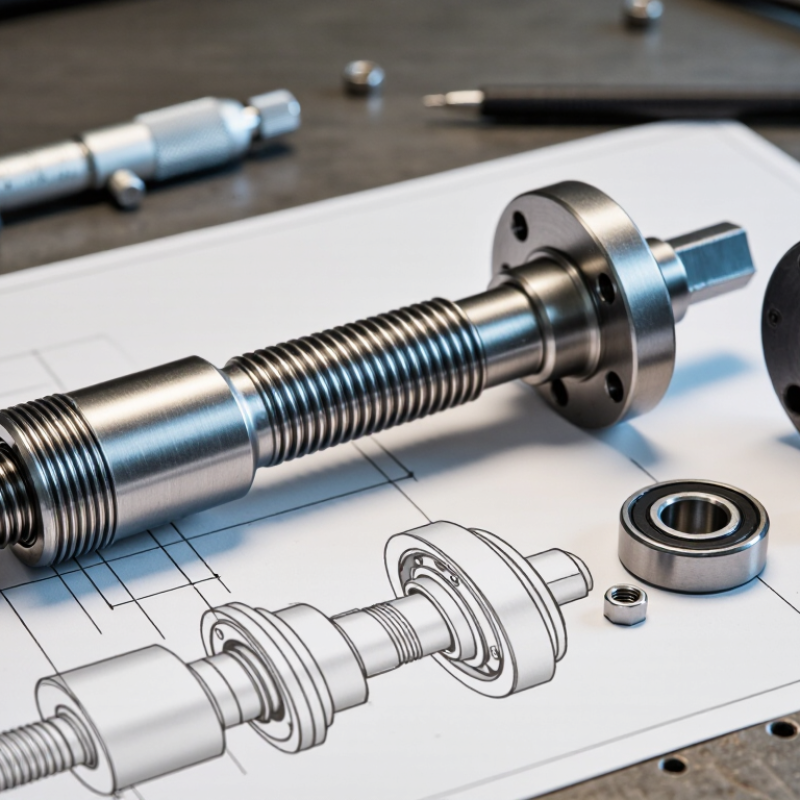
Understand the Function and Types of Motor Threaded Shafts
How to Choose the Right Motor Threaded Shaft
Understand the Function and Types of Motor Threaded Shafts
A motor threaded shaft transfers rotation while providing a point for fastening or motion control. Its threads may secure a pulley, gear, coupling, or other component. On a small motor, even a few millimeters of exposed thread can determine whether a part seats firmly or wobbles under load. The shaft’s function matters more than appearance.
Some shafts have a short threaded end for attaching a component with a nut. Others use a longer lead screw to convert rotation into straight-line movement, such as moving a small platform along guide rails. Thread forms and dimensions vary: check diameter, pitch, and thread direction against the mating part. Close is not always compatible. A mismatched pitch can feel acceptable at first, then bind or damage the connection.
Material, load, and operating conditions also affect the choice. Steel may suit higher loads, while lighter applications can use other materials. Check the motor drawing for shaft diameter, usable thread length, and tolerances; measure carefully if documentation is unavailable. A ruler may show length, but it cannot reliably identify thread pitch. One judgment call remains: the best shaft is not always the strongest, especially when added mass affects a small motor’s response.
Define the Shaft’s Load, Speed, and Operating Requirements
How to Choose the Right Motor Threaded Shaft
Define the Shaft’s Load, Speed, and Operating Requirements
A motor threaded shaft should be selected for the work it must do, not just its diameter. Record the axial load, any side load, and how loads change during each cycle. A carriage lifting a steady 20-kilogram fixture behaves differently from one stopping repeatedly under impact. Note both peak and continuous loads; sizing only for the average can hide a failure point.
Check rotational speed alongside travel distance and duty cycle. At higher speeds, vibration, heat, shaft whip, and nut wear become more likely, especially across long unsupported spans. Measure the distance between supports and compare the required speed with the shaft’s critical-speed limits. Keep a margin. Extra capacity can help, but oversized parts add inertia and cost without correcting poor alignment.
Operating conditions matter too. Note temperature, dust, moisture, lubrication access, and expected operating hours. These factors affect material choice, surface finish, and maintenance intervals. If the shaft starts and stops often, include acceleration and braking forces in your load estimate. Real machines rarely match a clean spreadsheet. Recheck assumptions against the actual equipment, and allow for uncertainty when measurements are rough. An overlooked side load can matter more than a small increase in rated axial force.
Compare Thread Size, Length, Material, and Tolerance
Choosing the right motor threaded shaft means checking more than its nominal diameter. Match the thread size and pitch to the mating nut or component; a similar-looking thread can still bind or loosen. Measure the usable shaft length from the correct shoulder or reference face, then allow for thread engagement and nearby parts. Too little engagement may weaken the connection, while excess length can interfere with a housing or coupling. Check the drawing or product specification rather than relying on a quick visual comparison.
Tips: Measure twice. Use a thread gauge when pitch is uncertain, and note whether dimensions are in millimeters or inches. A small unit mix-up can spoil an otherwise careful fit.
Choose material for the actual load and environment. Steel may suit many general applications, while corrosion exposure or elevated temperatures can call for a different specification. Tolerance matters, too: confirm the thread class and relevant shaft dimensions, including straightness or runout when the assembly requires accurate rotation. A shaft can meet its listed length and still perform poorly if it wobbles. It is easy to focus on the thread and overlook alignment; reviewing the full drawing can prevent that mistake.
How to Choose the Right Motor Threaded Shaft
Compare thread size, length, material, and tolerance before selecting a shaft.
Thread size: The chart shows nominal major diameters for common ISO metric coarse threads; the pitch is listed for each size. These are nominal dimensions, not measured finished-shaft diameters. Length: Choose a shaft and threaded length that accommodate the mounting space, parts being fastened, and required thread engagement. Material: Match strength, corrosion resistance, and operating conditions to the application. Tolerance: Specify the required thread class on the drawing; 6g is a commonly used external-thread class, but the mating thread and application determine the suitable fit.
Check Compatibility with the Motor and Connected Components
A motor threaded shaft must match more than the motor’s nominal size. Check the shaft diameter, thread type, pitch, and usable thread length against the motor’s output and the connected part. A shaft may screw in but still seat poorly if the thread pitch differs. That mismatch can damage threads or create unwanted movement.
Also compare the shaft’s shoulder, flat, keyway, and overall length with the assembly drawing. For example, a coupling may need a specific shoulder position to sit flush without rubbing the motor housing. Check the motor manufacturer’s dimensional data, then verify measurements with calipers where practical. A close visual match is not enough. I have seen small length differences complicate an otherwise simple installation.
Tips: Confirm rotation direction and expected load before choosing a shaft. Check whether the attached component needs a set screw, key, or clearance at the shaft end. Keep the motor and shaft specifications together during review.
If possible, test-fit the parts by hand before applying power. The connection should engage smoothly, without forcing or wobbling. Recheck alignment after tightening the coupling, since a slight offset can increase vibration and wear. When a dimension is unclear, pause and confirm it rather than guessing. That extra check can save time, though it is easy to skip when parts appear nearly identical.
Verify Installation, Maintenance, and Safety Requirements
How to Choose the Right Motor Threaded Shaft
Verify Installation, Maintenance, and Safety Requirements
A threaded shaft must match the motor and the driven component, not just look close enough. Confirm its diameter, thread pitch, usable length, and rotation direction against the equipment specifications. Small details matter. Check that the nut or coupling engages smoothly and that the shaft sits aligned, without side loading. Do not force it. Before installation or inspection, disconnect and secure the power source according to site procedures. Refit guards before operation, and keep hands and loose clothing clear of moving parts.
Tips: Use a thread gauge and caliper to check dimensions. Record the shaft’s orientation before removal. Follow the equipment maker’s guidance for lubrication and tightening; excess grease or torque can create problems.
After installation, run the motor briefly under controlled conditions and listen for rubbing or unusual vibration. Stop the equipment if the shaft wobbles, heats unexpectedly, or makes a new noise. Recheck fasteners and alignment only after the machine is safely stopped. During routine maintenance, inspect threads for flattening, corrosion, or debris, and look for wear where the shaft meets its support. A checklist helps, though it can still miss a subtle change. Compare findings over time, and replace damaged parts rather than relying on a tighter fit.
How to Choose the Right Motor Threaded Shaft - Verify Installation, Maintenance, and Safety Requirements
| Selection Area | What to Verify | Practical Data or Acceptance Check | Installation, Maintenance, and Safety Action |
|---|---|---|---|
| Thread system and size | Confirm the thread standard, nominal diameter, and pitch on the motor shaft and mating component. | Metric examples: M6 × 1, M8 × 1.25, and M10 × 1.5 are common coarse-thread sizes. Inch-thread examples include UNC and UNF; these are not interchangeable with metric threads. | Check the motor drawing or specification and use a matching thread gauge. Do not force a nut or coupling onto a thread that does not turn freely by hand. |
| Thread tolerance and fit | Verify the required thread tolerance class and fit for the application. | Metric thread tolerances are covered by ISO 965. The required tolerance depends on the shaft, mating part, and manufacturer’s design. | Inspect for damaged, flattened, or contaminated thread crests. Replace or repair parts only using an approved method; do not compensate for a poor fit by overtightening. |
| Thread engagement | Check usable thread length, fastener length, and clearance at the bottom of any blind hole. | The fastener must achieve the engagement specified by the motor or component manufacturer without bottoming out or contacting internal motor parts. | Confirm engagement with the actual assembled parts. Never assume that a longer bolt is safer; excess length can damage internal components or prevent the joint from clamping correctly. |
| Load and torque capacity | Confirm that the shaft and threaded joint can withstand the operating torque, axial load, and any shock or reversing loads. | Allowable loads and tightening torque are application- and design-specific; use the motor and coupling specifications rather than a generic torque value. | Use a calibrated torque tool when a specified torque is provided. Do not exceed the manufacturer’s limit or apply impact tools unless explicitly permitted. |
| Shaft dimensions and runout | Check shaft diameter, usable length, shoulder position, and allowable runout against the mating component. | Dimensional limits depend on the motor and driven equipment. Use the drawing or specified measurement limits for the particular assembly. | Measure with suitable inspection tools and keep bearing surfaces clean. Do not bend or side-load the shaft during fitting. |
| Alignment and balance | Verify that the connected part is aligned and suitable for the motor’s speed and duty. | Permitted misalignment and balance requirements depend on the motor, coupling, operating speed, and application. | Follow coupling instructions, check alignment before operation, and investigate unusual vibration, noise, or heating immediately. |
| Material and environment | Match shaft and fastener materials and finishes to the load, temperature, corrosion exposure, and operating environment. | Material strength, corrosion resistance, and coating can affect joint capacity and compatibility; verify these details from component specifications. | Use only approved lubricants, coatings, and thread-locking products. Check that any product used is compatible with the motor and operating conditions. |
| Installation condition | Inspect the shaft, thread, mating part, and contact surfaces before assembly. | Parts should be clean and free from burrs, cracks, corrosion, and visible thread damage. | Assemble without cross-threading. Keep debris and liquid away from motor openings, and follow the specified tightening sequence if one is provided. |
| Maintenance and inspection | Set inspection frequency according to duty cycle, environment, and equipment instructions. | There is no single inspection interval suitable for every motor or application; use the manufacturer’s maintenance schedule and applicable site requirements. | With the equipment safely isolated, check for loosening, wear, corrosion, cracks, abnormal vibration, and changes in alignment. Record findings and corrective work. |
| Electrical and mechanical safety | Identify electrical supplies, stored energy, rotating parts, and any hazards from the driven machine. | Isolation and verification procedures must follow the equipment documentation and applicable workplace rules. | Before installation or maintenance, isolate and lock out power, verify the equipment is de-energized, and allow capacitors to discharge as directed by the manufacturer. Refit guards before operation. |
| Final commissioning check | Confirm that the assembly is secure, clear of obstructions, and ready for a controlled test. | Acceptance criteria should match the motor and driven-equipment specifications; stop if there is unexpected noise, vibration, heat, or movement. | Keep personnel clear of rotating parts, start under controlled conditions, and recheck the assembly after shutdown according to the maintenance procedure. |
Note: Thread examples are common nominal sizes, not a recommendation for a particular motor. Always use the motor and mating-component specifications for dimensions, tolerances, engagement, loads, and tightening torque.
