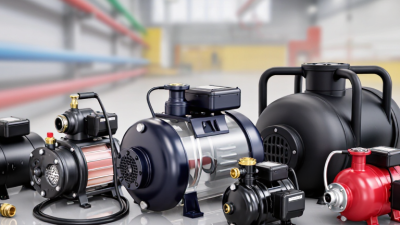
How to Choose the Right Drainage Pump?
Choosing the right drainage pump is less about buying the largest unit and more about matching it to the water, site, and discharge route. A pump that looks powerful on a label may struggle when water contains grit or must travel through a long, narrow hose. NOAA’s 2023 U.S. Billion-Dollar Weather and Climate Disasters report counted 28 disasters, with estimated losses of $92.9 billion. Those figures are national, not a forecast for any one property, but they show why dependable water removal matters. On site, even a few centimeters of standing water can threaten stored tools, electrical equipment, or a finished basement. Small details matter.
The U.S. Department of Energy’s Improving Pumping System Performance sourcebook notes that pumping systems use a substantial share of electricity worldwide. That estimate covers pumping systems broadly, not drainage pumps alone; still, it underlines why efficiency deserves attention alongside purchase price. Hydraulic Institute guidance also emphasizes matching pump performance to the system’s actual operating conditions. Check the required flow rate, total head, solids size, power supply, and expected run time before choosing a model. For example, a shallow flooded garage with a short hose has different needs from a muddy excavation draining uphill. There is no universally “best” pump. And specifications can mislead. A careful choice starts with measurements, yet real sites are messy, and assumptions about debris or water level may prove wrong. Allow for that uncertainty, and compare manufacturer performance curves rather than relying on one headline capacity figure.
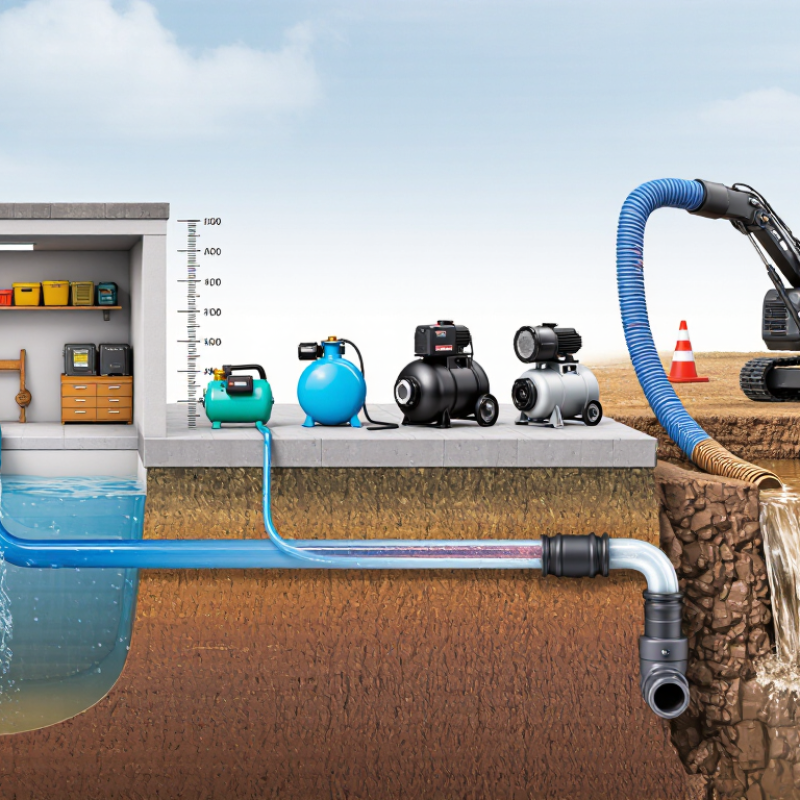
Define Design Flow from Peak Inflow, Stated in L/s or m³/h
How to Choose the Right Drainage Pump?
Define design flow from the highest credible inflow, not the daily average. A pump sized for average conditions may fall behind when several drains discharge together. For a sump, record the water level rise over a timed interval, then use the tank’s dimensions to estimate incoming volume per second. Check the result during rain or equipment washdown if those events affect inflow. Small differences matter. A narrow pit can fill quickly.
State the required flow in L/s or m³/h, and keep the units consistent when comparing pump data. One L/s equals 3.6 m³/h. For example, a measured peak of 2 L/s is 7.2 m³/h. Treat that as the starting design flow, then confirm the pump can deliver it at the actual operating head, not merely at a listed maximum. Include simultaneous inlets where they are likely, but avoid adding a large, unexplained safety factor. Real inflow records are often incomplete; note the assumptions and revisit them after observing the system in service.
How to Choose the Right Drainage Pump? – Define Design Flow from Peak Inflow, Stated in L/s or m³/h
Start with the highest expected inflow to the sump or drainage system. The examples below apply an illustrative 10% planning allowance; this is not a universal requirement. Confirm the appropriate allowance using site data, applicable codes, and engineering review.
| Example Application |
Peak Inflow (L/s) |
Illustrative Allowance |
Design Flow (L/s) |
Design Flow (m³/h) |
Selection Consideration |
| Residential basement sump |
0.8 |
10% |
0.88 |
3.17 |
Check inflow during heavy rain and confirm the pump can pass any expected solids. |
| Small commercial stormwater pit |
5.0 |
10% |
5.50 |
19.8 |
Base peak inflow on the contributing area, rainfall assumptions, and drainage layout. |
| Underground parking drainage sump |
12.0 |
10% |
13.2 |
47.5 |
Assess ramp runoff, washdown water, and whether multiple pumps are required for duty and standby. |
| Light industrial wastewater collection pit |
25.0 |
10% |
27.5 |
99.0 |
Confirm liquid characteristics, solids content, operating cycles, and discharge requirements. |
| Large process-area drainage sump |
40.0 |
10% |
44.0 |
158.4 |
Use measured or engineered peak inflow and verify the system’s hydraulic and electrical capacity. |
Calculate Total Dynamic Head from Lift, Pipe Length, and Fitting Losses
Total dynamic head (TDH) is the height your pump must overcome, plus losses as water moves through pipes and fittings. Add static lift, straight-pipe friction, and fitting losses at the intended flow rate. The U.S. Department of Energy’s Improving Pumping System Performance sourcebook estimates that pumping systems use nearly 20% of global electricity, underscoring why accurate sizing matters. Oversizing can waste energy; undersizing may leave the outlet weak.
For a practical estimate, assume a 20-foot lift and 60 gallons per minute through 100 feet of 2-inch pipe. If a friction chart gives 8 feet of loss per 100 feet at that flow, and fittings add an equivalent 25 feet of pipe, friction totals about 10 feet. Estimated TDH: 30 feet. Use Crane Technical Paper No. 410 for fitting-loss coefficients, and check the actual pipe material and diameter. This estimate can still miss losses from a clogged screen or changing water level.
Tips: Use the pump’s performance curve at your calculated flow and TDH. Include the discharge point’s elevation and any required outlet pressure. Measure rather than guess where possible. Recheck the calculation after installation.
Match Pump Type and Solids-Passage Diameter to the Debris
A drainage pump should be selected for the debris it will actually encounter, not just the water volume. A clean-water pump suits rainwater with little sediment. For muddy runoff, leaves, or small stones, choose a dirty-water model with a stated solids-passage diameter. That figure describes the largest solid the pump can pass; it does not guarantee that every shape will move freely.
Check the debris closely. A pump rated for 20-millimetre solids may handle small gravel, yet long grass or thin strips of cloth can still wrap around the impeller. Fibrous material needs special attention. A vortex or solids-handling design may reduce clogging, while a cutting mechanism is better suited to stringy waste where the pump is designed for it. More capacity is not always better. Oversizing can raise cost and energy use without solving the wrong pump-type choice.
Compare the pump’s published passage size with the largest likely debris, then allow a practical margin. Measure stones or scraps on site if possible; estimates can be optimistic. Check the intake screen, too, because a narrow screen can block material before it reaches the impeller. For a drainage pit, note whether debris settles at the bottom or floats near the surface. The selection is not perfectly tidy: mixed debris may call for screening, cleaning, or a different pump arrangement. Verify the manufacturer’s limits for both solids size and material type before installation.
Check Submergence, NPSH, and IP68 Rating Under IEC 60529
Choosing a drainage pump starts with the water level and the conditions inside the sump. Check the pump’s minimum submergence in its manual; too little water above the inlet can create a vortex and draw in air. That may cause unstable flow, noise, or overheating. Measure the lowest operating water level, not just the level after a storm. A few centimeters can matter.
NPSH matters even with a submerged pump. The available inlet pressure must exceed the pump’s required NPSH, with a suitable margin. Check the pump curve and account for water temperature, inlet restrictions, and any lift or pipe losses. Real installations are not always tidy; a clogged screen or narrow hose can change performance. If figures are unclear, ask a qualified pump specialist to review the operating point.
Tips: Confirm the required submergence and NPSH margin against the manufacturer’s data. An IP68 rating under IEC 60529 indicates protection against dust and immersion under specified conditions, but it does not mean unlimited depth or time. Check the stated immersion limits, cable entry, and installation instructions. Keep the connection dry and inspect the cable seal regularly. Small details count.
Verify Duty-Point Performance Using ISO 9906:2012 Test Criteria
A drainage pump’s duty point is the flow and head it must deliver together, not two figures considered separately. Before purchase, compare the required operating point with the pump’s published curve. Then ask how that curve was verified. ISO 9906:2012 sets acceptance test criteria for rotodynamic pump performance, including measured flow, head, and power. The applicable acceptance grade and tolerances should be agreed before testing, not chosen after results arrive.
For a useful comparison, confirm the test used the specified speed and impeller diameter, and request the recorded results near your duty point. A test far from that point may not tell you enough. Check the measurement method and stated uncertainty, too.
Small differences matter.
For example, a pump that meets flow in a clear-water test may behave differently in a sump with debris, air, or changing water levels. ISO testing verifies controlled hydraulic performance; it cannot recreate every site condition. This distinction is easy to overlook, especially when a neat test sheet looks conclusive. Tie the test evidence to your actual operating range, then check whether the installation, controls, and pipework can support it.